
Suspension
I served as the suspension lead in the 2019 season. My main goals were to improve the vehicle’s low speed turn radius and to solve the mystery of the failing rear suspension links.
Low Speed Turning Radius
I developed an experiment to determine the effect of steering angle and Ackermann percentage on the vehicle’s low speed turning radius. A custom upright was designed and built for the experiment, allowing extreme steer angles up to 50 degrees to be acheived and allowing for the Ackermann percentage to be adjusted.
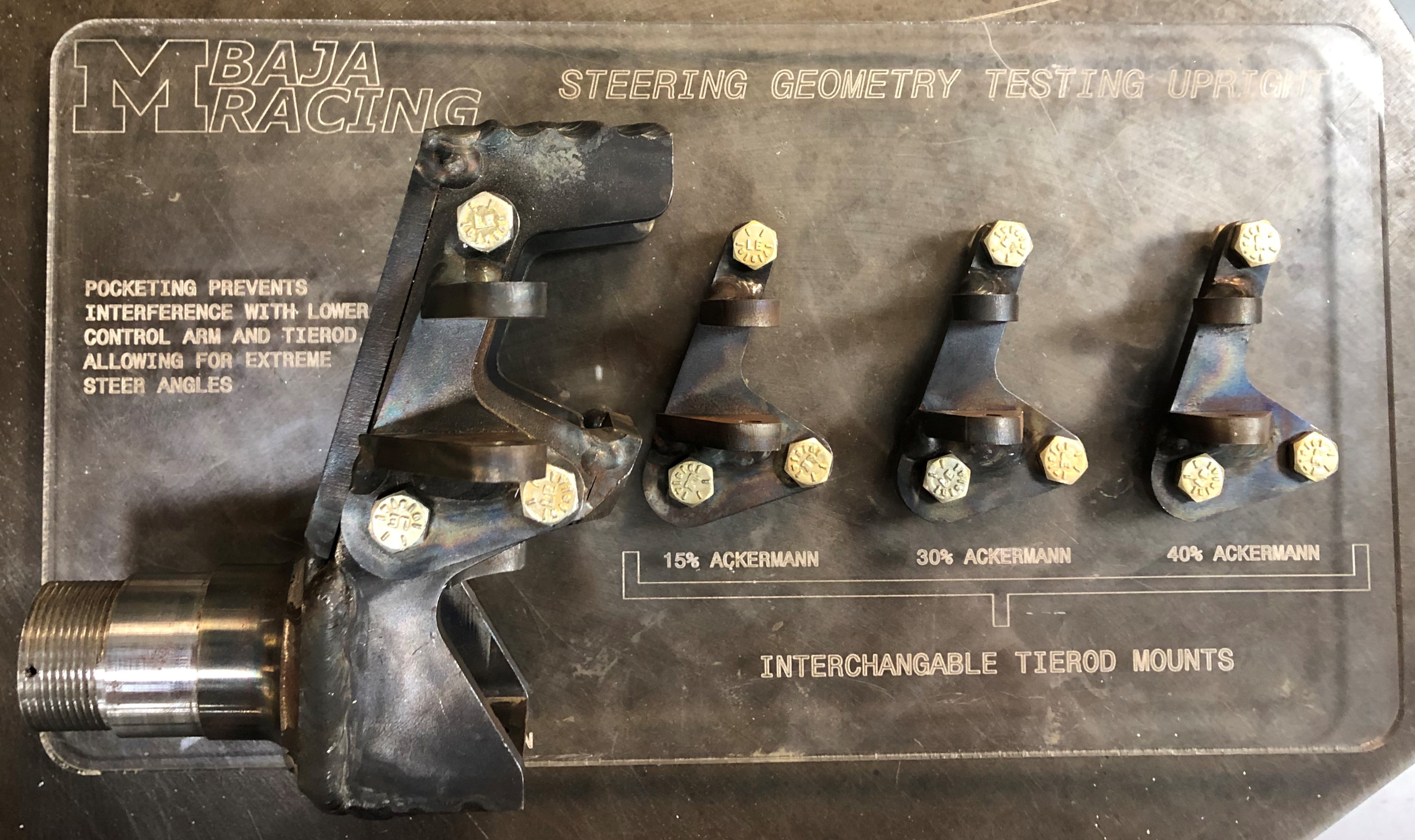
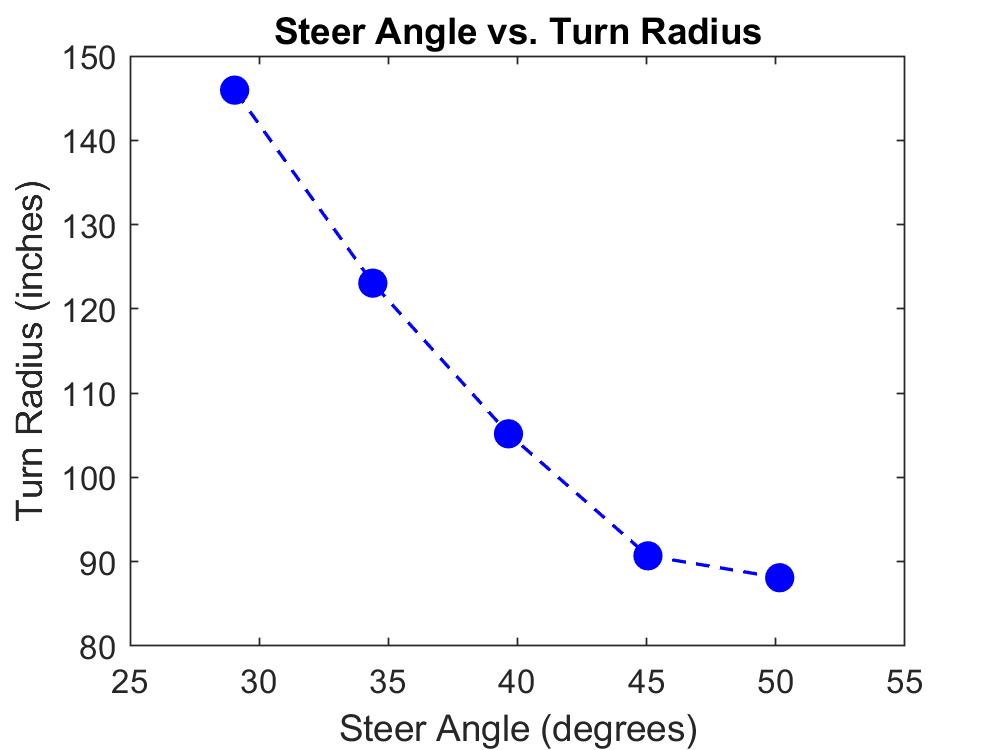
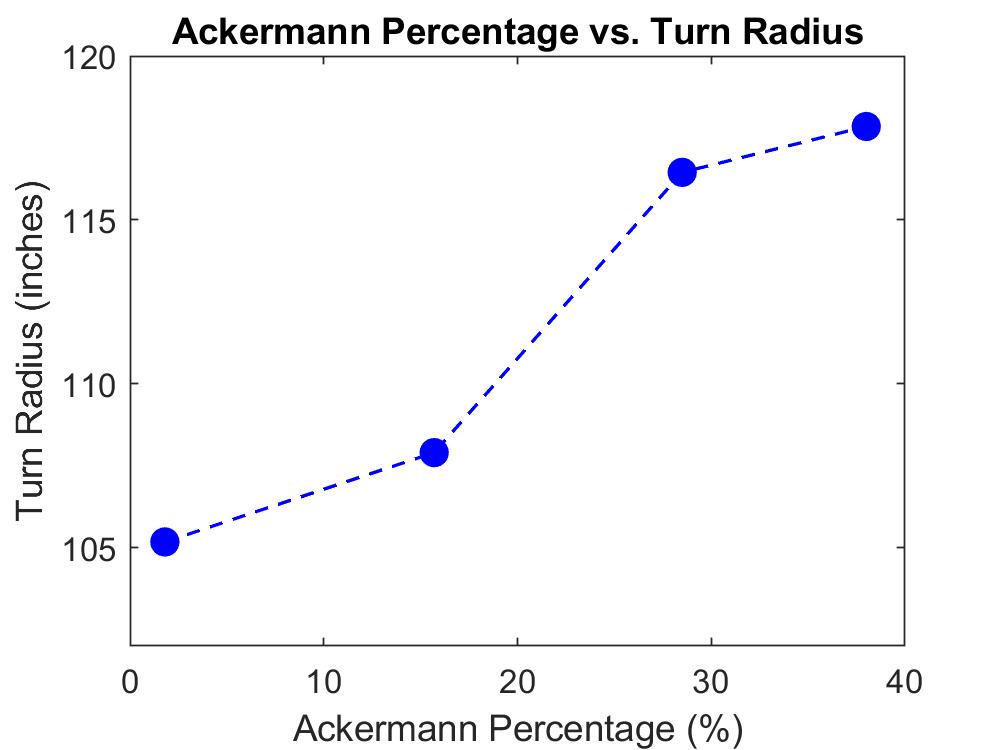
The vehicle’s turning radius was measured as each parameter was independently adjusted. It was determined that steer angles larger than 45 degrees gave minimal improvements to the turn radius. Increasing Ackermann percentage beyond a parallel-steer condition was shown to yield a larger turn radius. The plots shown below illustrate these results.
The results of this exeriment were used to design the steering kinematics on the 2019 competition vehicle, yielding a 4.5 foot reduction in the turn radius over the previous vehicle (a 37% improvement).
Rear Suspension Load Cases
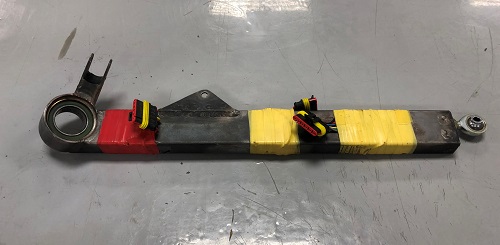
In the 2018 season, we saw many failures to our H-arm, a critical link in the vehicle’s rear suspension. The finite element analysis (FEA) run on the H-arm to check its strength showed that the link would be strong enough to withstand all of our tested load cases. Yet, the links were yielding under normal driving loads commonly seen during a race. This led us to believe that the load cases used in our FEA were not accurate to the loads actually seen on the vehicle. To correct this issue, I laid strain gauges on the rear suspension links of a previous vehicle, enabling us to collect data on the actual loads acting on the rear suspension.
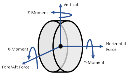
Strain data was collected while driving the vehicle over obstacles to simulate the worst case loads we would see in a competition. That strain data was post-processed using MATLAB to calculate the forces and moments acting on the rear wheel in the three standard vehicle axes. The peak forces and moments from the test data were found and used to set new test cases for use in the suspension link strength analysis.
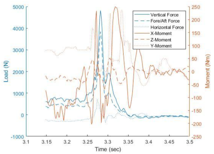
The test data revealed our previous load cases were severely underconservative in a particular direction of loading. Using the new load cases, we reanalyzed the failed H-arm design in FEA. The reanalysis showed that the link would yield at the same location we observed the links yielding on the car, confirming our hypothesis that innacurate load cases were to blame for the failures. We then redesigned the H-arm to improve its strength, ensuring it would be able to withstand all driving loads without yielding. The redesigned arm was used on the 2019 vehicle through extensive testing and at all three competitions with zero failures.